

IEC62109&VDE0126 And IEC60990 Inverter Safety Characteristic Analyzer Operating Instructions
Product Details:
| Place of Origin: | DONGGUAN |
| Brand Name: | KINGPO |
| Certification: | ISO9001 |
| Model Number: | C5010 |
Payment & Shipping Terms:
| Minimum Order Quantity: | 1 |
|---|---|
| Price: | 50000000 |
| Packaging Details: | 2000*2000*2000CM |
| Delivery Time: | 30DAY |
| Payment Terms: | T/T |
| Supply Ability: | 100PCS |
- Description
- Reviews (0)
Description
Detail Information
Safety Characteristics Analysis instrument
,
IEC60990 Characteristics Analysis instrument
,
IEC62109 Characteristics Analysis instrument
Product Description
IEC62109 and VDE0126 and IEC60990 inverter safety characteristic analyzer Operating Instructions
1, summary
0126-1M Photovoltaic array inverter Safety Characteristics Analysis instrument is a special measurement equipment developed according to the inverter related identification test standards IEC62109 and VDE0126 and IEC60990, an inverter for measuring the residual current of photovoltaic array inverter, distributed PV inverter, contact current, insulation resistance (current), overheating fire danger current, can measure output power up to 1000kVA.
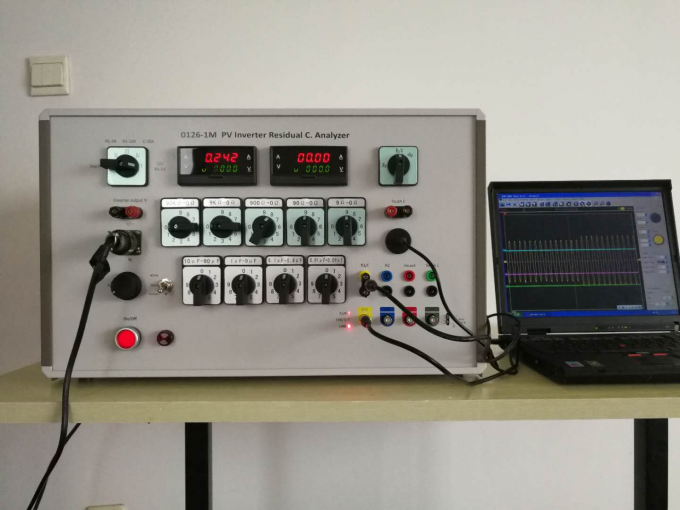
0126-1M Inverter Safety Characteristic Analyzer is equipped with a four-channel USB oscilloscope, external to any laptop, you can test and observe the residual current, protector break time of the inverter, contact current peak and frequency, etc.
The 0126-1M can also external a user selected oscilloscope to replace the laptop.
2. function
The 0126-1M Inverter Safety Characteristics Analyzer has the following test functions required by IEC62109 and VDE126 standards:
- Continuous residual current R1 and split time test shall be performed according to IEC62109-2 Article 4.201.3.1.4
- Resistance process residual current R2 and break time shall be tested according to IEC62109-2 Article 4.201.3.1.4
- Test the fire hazard residual current of the isolated inverter in accordance with IEC62109 # 4.201.3.1.2
- 30mA contact current test by IEC62109-2 and IEC60990 (measurement network: IEC60990 Fig4, U1 and U2)
- Test the inverter for insulation resistance or insulation leakage current (30mA) according to IEC62109-2 Section 4.201.2.
- Continuous tolerance residual current and break time can be tested as per IEC62109 according to VDE0126-1-1 supplement
It has a built-in four-channel USB oscilloscope, and each channel measurement function is as follows:
The CH1-yellow input was used to measure the current waveform of R1 / C
The Ch2-blue input was used to measure the current waveform of R2
The Ch3-red input is used to measure the current waveform of the inverter output, which measures the current waveform compared to the R2 current waveform;
The Ch4-green input is used to measure the voltage peak of Touch C leakage current, voltage true value.You can derive the current peak and the current effective value by dividing them by the 500 Ω sampling resistance in the IEC60990 circuit.
- The user oscilloscope may be connected; and provide R1, R2 trigger signal;
- External user ammeter, including calibration or DC component ammeter;
- External user load resistance box, up to 10A / 700V;
- A rectifier circuit is provided that can be used to verify the residual current effective value and DC components.Always turn off this function (put the backplane rectifier circuit control switch at the open position).
3. Residual current measurement
0126 The resistance residual current load circuit and the tolerance residual current load circuit are specially adopted. When the inverter input voltage is 500V-700V, the constant residual current R1 can be generated in a wide range of 0.01A-3A.
When measuring a photovoltaic inverter with an output power of 250kVA-1000kVA, the R1 load circuit needs to give an R1 current of 2.5A-10A, and the maximum power consumption of the R1 load will reach 3500W.For this purpose, the instrument is equipped with a special external load resistance box, which is a manual continuously adjustable four-tube slide wire resistance box with 1A,2.5A, 5A, 10A, corresponding resistance values of 10 Ω -410 Ω, 10-10 Ω -210 Ω, 10-10-110 Ω, 10 Ω -60 Ω, 10A maximum consumption power of 5000W.It is also simple to use. Adjust the panel function knob to 10A, connect the external resistance box from the backplane, the adjustment and penetration of R2 and true effective value reading, USB oscilloscope will monitor the inverter protection circuit break time.The resistance box has a chemical fiber resistance position indication, to remind the operator to accurately understand the position of the sliding wire resistance sliding arm before the use, to avoid overload.
The instrument is equipped with a four-ten-bit capacitance R1 load loop with a capacity adjustment range of 0.01 F-9.99 F. According to the capacitor current formula I=. C. U, the input voltage is 350V, 50Hz, and the capacitor current at the time when the capacitor is transferred to 9.9 F is 11A.This load loop is mainly used to measure the residual current R1 due to overload. Because the capacitor current is a reactive loss current.
0126 The instrument is equipped with a continuous adjustable power resistance R2, providing the mutant residual current R2 of 30mA, 60mA, and 150mA required in the IEC62109 standard, meeting the requirements of the IEC62109-2 and VDE0126-1-1 test standards.
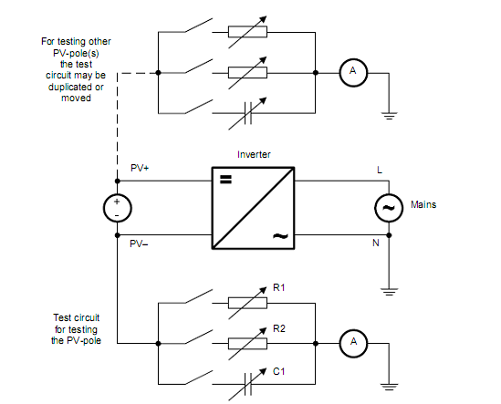
0126 Two four and a half AC voltage / current dual display digital meters are placed on the left and right sides of the instrument panel.The digital table on the left is used to measure the true effective value R1 continuous residual current, R2 burst current and contact current (Touch Current) and insulation leakage current, while measuring the inverter input voltage.The right digital display meter measures the R1 residual current in the range 10A, and also measures the output voltage of the inverter.See Figure 1 for the measurement circuit diagram for the IEC62109-2:2011 standard.

Figure 1 IEC62109-2 residual current measurement circuit diagram
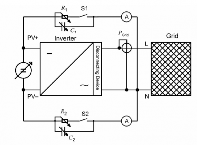
See Figure 2 for VDE0126-1-1.

Figure 2 VDE0126-1-1 residual current measurement circuit diagram 1
The USB oscilloscope of four-channel 60M built in 0126-1M measures the R1 resistance residual current, R1 tolerance residual current and R2 resistance burst current, respectively. The more important function of the USB oscilloscope collection card is to monitor the break time of the residual current R1 due to burst R2 current, which has the function of real-time, intuitive, accurate and fast monitoring operation.
The continuous adjustable resistor R2 also provides a starting value of 20mA for measuring the constant residual current, which accurately setting the upper and lower threshold for the residual current split current.
In order to monitor the action time of the inverter output protection device, the instrument is equipped with the inverter output connection port and transmits the output voltage to the oscilloscope port CH3 via the internal isolation transformer with an input voltage of 630V.
The 0126-1M instrument is equipped with a load circuit overload control. When the load power resistance is overheating exceeds 70℃ due to overload, the temperature control circuit automatically cuts off the load circuit until the temperature is below 70℃ and the instrument automatically returns to normal.
The 0126-1M instrument has a built-in four-channel oscilloscope. After installing a special measurement program, the measurement instrument can measure the separation value and separation time, residual voltage frequency and voltage amplitude, voltage waveform, etc., and can conduct background processing of data on the computer notebook, including downloading data, saving data and printing data.The oscilloscope parameters are be in relevant information.
The bottom right of the instrument panel is the output of the oscilloscope, as shown:
The CH1-yellow input was used to measure the current waveform of R1 / C
The Ch2-blue input was used to measure the current waveform of R2
The Ch3-red input is used to measure the current waveform of the inverter output, which measures the current waveform compared to the R2 current waveform;
The Ch4-green input is used to measure the voltage peak of Touch C leakage current, voltage true value.You can derive the current peak and the current effective value by dividing them by the 500 Ω sampling resistance in the IEC60990 circuit.
Located above the USB oscilloscope measurement port are the four measurement output ports corresponding to the oscilloscope CH1-CH4, connecting each measurement output to the corresponding input of the USB oscilloscope with the NFC converter and a special cable to measure each signal waveform.
If the customer wants to outconnect its own oscilloscope, it can remove the NFC cable to one end of the USB oscilloscope and transfer it to the oscilloscope.
This USB oscilloscope is floating ground with sufficient electrical isolation to connect the external oscilloscope directly.However, it is still recommended to float the oscilloscope (disconnect the oscilloscope grid ground).
The 0126-1M instrument is equipped with residual current overload sound and light alarm function, which is set at 2.5A. When the R1 load current reaches 2.5A, the buzzer alarm in the panel will sound and light alarm to remind the operator that the load loop may overload and heat.The operator can turn off the buzzer alarm through the control switch on the backplane.Users can also set up the alarm current according to the instructions,
According to VDE126 standard, to avoid resistance load overload, the R1 + C1 function is set by the switch of the backplane.
This instrument connects the rectifier diode in the R1 load loop as required by IEC62109 to analyze the residual current DC component and the true effective value.During normal test, the rectifier diode shall be cut off by the switch of the instrument.
4. insulation resistance test
0126-1M may also measure the inverter insulation resistance or insulation leakage as per IEC62109 Article 4.201.2
Current current (30mA).Using a five-stage decimal step adjustable power resistance box on the instrument panel, resistance from 0 Ω to 99999 Ω can be generated with an error of 1%.Adjust the resistance so that the leakage current reaches 30mA specified in standard or adjust the resistance value to the value specified in standard to see if the leakage current exceeds 30mA.
5. Contact current measurement
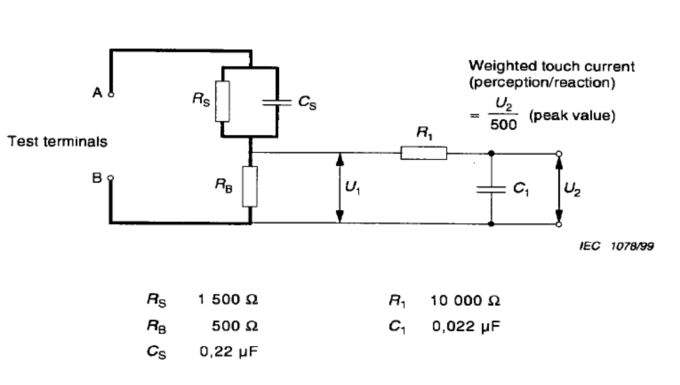
0126-1M integrates contact current measurement functions to measure the inverter contact current (also known as protected current or leakage current) in accordance with clause 4.201.3.1.1 or IEC60990.Measurement network Press Figure 4 in IEC60990: perception-weighted contact current measurement network, see the figure below.

According to the requirements of the IEC60990, the 0126-1M can use a digital display ammeter to measure the effective value of the contact current directly, and it can also measure the peak voltage U of the contact current with a USB oscilloscope2And frequency, press U2The / 500 relationship yields a frequency-weighted contact current.
6. Measurement items and measurement scope
Measurement items and measurement scope that meet the requirements of IEC62109-2 standard:
- R1 resistive residual current: 1.0A (step continuously adjustable)
- R1 resistive residual current: 10A (step continuously adjustable)
- Residual current: 10A (step continuously adjustable)
- R2 resistive burst residual current (30mA): 10-50mA (continuously adjustable)
- R2 resistive burst residual current (60mA): 20-80mA (continuously adjustable)
- R2 resistive burst residual current (150mA): 80-200mA (continuously adjustable)
- Residual current split time resolution: 0.1ms (60MHz four-channel USB oscilloscope)
- Test-tested inverter power:
- ≤100kVA
- ≤250kVA
- 1,000 k V A (plug-in standard load box)
- Contact current: 0-100mA
The built-in IEC60990 Figure 4 sensing weighted contact current measurement network to measure the fourth port of the USB oscilloscope and effective values are measured with ammeter 1 and voltmeter 1.
7.USB oscilloscope and measurement output port
The built-in model of the DSO-3000 series four-channel USB oscilloscope is used to measure the dynamic waveform.The four-channel measurement function is:
The CH1-yellow input was used to measure the current waveform of R1 / C
The Ch2-blue input was used to measure the current waveform of R2
The Ch3-red input is used to measure the current waveform of the inverter output, which measures the current waveform compared to the R2 current waveform;
The Ch4-green input is used to measure the voltage peak of Touch C leakage current, voltage true value.You can derive the current peak and the current effective value by dividing them by the 500 Ω sampling resistance in the IEC60990 circuit.
The panel is equipped with a waterproof round USB oscilloscope output port for connecting a laptop or computer as a display terminal for the USB oscilloscope.Each measurement signal can be displayed after the laptop has installed the randomly provided special software.The performance parameters for the USB oscilloscope can log on: http: / / www.hantek.com.cn
Located above the USB oscilloscope measurement port are the four measurement output ports with colors corresponding to the oscilloscope CH1-CH4.Each signal waveform can be measured by connecting each measuring output to the corresponding input of the USB, respectively, with the NFC converter and the dedicated oscilloscope.
If the customer wants to attach its own oscilloscope, remove the NFC cable to one end of the USB scope and transfer it to the oscilloscope.
This USB oscilloscope is floating ground with sufficient electrical isolation to connect the external oscilloscope directly.However, it is still recommended to float the oscilloscope (disconnect the oscilloscope grid ground).
8. Display the instrument scope and precision
Table 1 (Voltage and current dual display)
- AC current effective value: 0-999.9mA r.m.s ,0.3%F.S.±2 digit
- AC voltage: 0-999.9V r.m.s ,0.3%F.S.±2 digit
Table 2 (Voltage and current dual display)
- AC current effective value: 0-9.999A r.m.s ,0.3%F.S.±2 digit
- AC voltage: 0-999.9V r.m.s ,0.3%F.S.±2 digit
- Ammeter frequency Bandwidth: 500kHz
- Frequency measurement (USB oscilloscope): 60MHz, ± 1%
- Sampling rate: 1 time / 2.5s
- Overscale display: O.L/O.H
- Polarity display: The- -symbol displays automatically
- Alarm settings 2.5A r.m.s O.H
- alarm display O.H
USB oscilloscope
- Base accuracy of horizontal system: ± 50ppm
- Equipped with self-calibration with 1kHz / 2Vp-p square wave output
9. calibration
Instrument calibration
The backplane of this instrument is equipped with external ammeter port, delivered by short-circuit rod.The user can connect the true effective value ammeter through this port or connect the high precision ammeter for calibration
oscilloscope
The calibration of the four-channel USB built in this instrument is exactly the same as the universal oscilloscope calibration, which only puts the oscilloscope in operation and input the oscilloscope calibration signal into the corresponding CH port.
Note that because the waveform is non-sinusoidal wave, non-triangular wave and non-square wave at the input of the inverter, the traditional electric school calibration method (integral method) is not perfect, and when there is an objection, the thermal power calibration method should be adopted.
- safeguard
- The instrument is a Class I safety protection design, and all operator-contact metal parts of the enclosure are subjected to the electric resistance strength voltage of 1500VAC;
- The measuring circuit of this instrument is floating ground design and can be directly connected to oscilloscope, etc;
- This instrument is equipped with a leakage security switch to provide cut-off protection when the measurement circuit overload short circuit or the ground leakage current exceeds the limited value, requiring manual reset;
- A 2.5A fuse is built in the power input socket of the instrument for overload short circuit inside the instrument (e. g. instrument, 12VDC power supply).
- The power resistance R1 is equipped with a 70℃ temperature control switch. When the power resistance surface temperature exceeds 70℃, the R1 load circuit is cut off, and after the temperature is below 70℃, the switch is automatically reset.
- The contact current (Touch C) measurement input has a steady voltage zer diode, which, when the measurement mistakenly contacts the high potential, instantly breaks the 0.2A fuse to protect the precision resistance of the weighted filter network.Note that fuses above 0.2A.
- The R1-3A measurement circuit has a 3A fuse, providing overcurrent protection.
- The R1-10A, C-10A measurement circuit is provided with a 10A fuse, providing overcurrent protection.
- The instrument panel is equipped with a buzzer. When the alarm prompt exceeds 3A in R1, the user can operate in the digital display meter panel and set the alarm current by itself.
11, service environment
- temperature:0-50℃
- Humidity: 80%R.H.(No condensation)
- Air pressure: 96-106k Pa
- Power supply: 220V ± 10%, single-phase + protection ground
- When using the external load box, pay attention to ventilation, and do not cover it with clothes.
12, USB oscilloscope OS
- Install the randomly supplied application
- Operating system required by drivers and applications: Windows98 / ME / 2000 / XP / VISTA
13. Safety matters
- IEC61010 / GB4793 compliance
- This measuring instrument is Class I equipment and must be connected to the power supply with protected ground.
- Protection level: IP20
- The power socket fuse is F2A / 250V and shall be replaced as per this specification after the circuit breaker.
- Load circuit fuse is F3A / 250V, F10A / 250V, and shall be replaced after circuit breaker.
- The contact current network fuse is 200mA / F250V
- Pressure resistance strength: 1,500 V a.c
- Insulation resistance: 100M Ω / 500Vd.c
Instructions for using the external high-power slide wire resistance box
The instructions for the external high power sliding wire resistance box are composed of four synchronous linkage sliding wire resistance, each rated current of 2.5A, resistance of 200 Ω, rated power of 1250W. After the four resistors in parallel, the maximum current is 10A and the power reaches 6000W.In order to meet the use under different current conditions, the four power resistance and resistance values are adjusted to meet the test requirements of different currents.

Switch order diagram
| 2.5 | 5 | 7.5 | 10 | |
| 3-4 | × | |||
| 5-6 | × | × | ||
| 7-8 | × | × | × |
| 2.5 | 5 | 7.5 | 10 | |
| Range of impedance | 0-240Ω | 0-120Ω | 0-75Ω | 0-55Ω |
| current range | ≦2.5A | ≦5A | ≦7.5A | ≦10A |
| Method of impedance | one way | Second parallel | Three road parallel | Four way parallel |
| maximum input voltage | 600V | 600V | 560V | 550V |
Note: If a low current is measured at a gear, the slip resistance to the maximum resistance does not give a small current, for example:
In gear 5A, if the test voltage is 3A, the input voltage cannot be higher than gear 360V;2.5A, and if the test current is 1.2A, the input voltage cannot be higher than 288V.
At this time, the next gear of high resistance value, for example, 5A gear, test current of 3A, gear 2.5A, but note that it should not exceed 120% of the rated current; or at this gear test, remove the short circuit rod and external resistance to increase the circuit resistance value.
IEC62109 and VDE0126 and IEC60990 inverter safety …


Reviews
There are no reviews yet.