

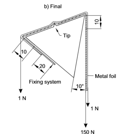
IEC 61558 Figure 6 Mandrel test For Checking Mechanical Withstanding Of Insulating Materials In Thin Sheet Layers
Product Details:
| Place of Origin: | China |
| Brand Name: | KingPo |
| Certification: | calibration cert |
Payment & Shipping Terms:
| Minimum Order Quantity: | 1 |
|---|---|
| Packaging Details: | safety carton pack or plywood box |
| Payment Terms: | T/T |
- Description
- Reviews (0)
Description
Detail Information
Standard:IEC 61558 Figure 6Weight:100N*1,50N*1( The Pulling Force Of 50N, 100N, 150N Can Be AchievedRotate Angle:230°Test Mandrel:Triangle Bar With A Tip Including Metal FoilTest Voltage:At Least 5 KVThin Sheet:70 Mm In WidthHigh Light:
av test equipment
,
tv test equipment
Product Description
Test arrangement for checking mechanical withstanding of insulating materials in thin sheet layers
1.Application:
This device is used to test the Insulation anti damage strength verification for non separable thin layer materials.Confirm to IEC60950 Safety of information technology equipment, IEC60065-1 Audio, video and similar electronic apparatus-Safety requirements and IEC61558-1-Fig6
Test procedure
- Installation
* This tester should be placed on a level table
- Preparing works
1. For the mandrel test, three separate test specimens of thin sheets 70 mm in width shall be supplied
2. Rotate the device to original position
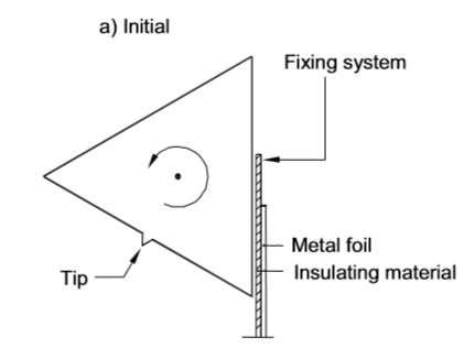
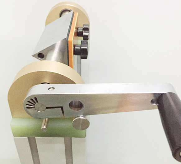
(Initial)
2.1) According to the standard, install the sample and foil,then hang the corresponding weight (50N /100N/ 150N).
2.2) The mandrel shall be slowly rotated forwards and backwards three times for 230° without jerking motion. If the specimen breaks at the clamping device during the rotation, the test shall be repeated. If one or more specimens break at any other place, the test is not fulfilled.
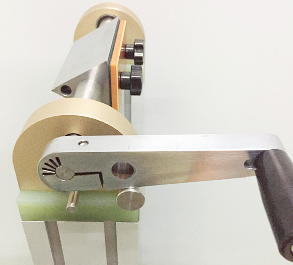
(final)
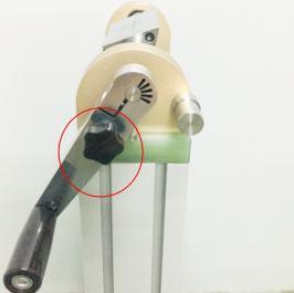
2.2)While the mandrel is in its final position,plug the metal bar into hold of the mandrel,within a minute following the final positioning, a dielectric strength test voltage shall be applied for 1 minute as described in IEC61558-clause 18.3 between the mandrel and the metal foil as follows:
– a test voltage of at least 5 kV or the applicable test voltage of Clause 18.3 multiplied by 1,35 for a specimen consisting of several non separable layers ( at least 3 layers) whichever is the greater;
– a test voltage of at least 5 kV or the applicable test voltage of 18.3 multiplied by 1,25 for a specimen consisting of 2/3 of the number of at least 3 separated layers whichever is the greater;
– a test voltage of at least 5 kV or the applicable test voltage of 18.3 multiplied by 1,25 for a specimen consisting of one layer of the number of 2 separated layers whichever is the greater.
No flashover or breakdown shall occur during the test, and corona effects and similar phenomena shall be disregarded


Reviews
There are no reviews yet.