


IEC61010-031 Single Core Probe Cable Rotational Flexing Tester
Product Details:
| Place of Origin: | China |
| Brand Name: | Kingpo |
| Certification: | Certificate of ISO17025 |
Payment & Shipping Terms:
| Minimum Order Quantity: | 1 |
|---|---|
| Price: | To be quoted |
| Packaging Details: | safety carton pack or plywood box |
| Delivery Time: | 7 working days |
| Payment Terms: | T/T |
| Supply Ability: | 20 sets per month |
- Description
- Reviews (0)
Description
Detail Information
Single Core Probe Cable Tester
,
IEC61010-031 Rotational Flexing Tester
Product Description
IEC61010-031 Single Probe Cable Rotational Flexing Tester
The patent discloses a watch probe cable tensile torsion wear-resistant testing machine, including a testing machine shell, the inner part of the testing machine shell is provided with a servo motor and a turbine reducer, the front end of the testing machine shell is provided with a control panel, the bottom of the control panel is connected with a base, the four corners of the base are supported by a support, and the center below the base is connected with a cylinder tray through the support, the right end of the base extends out of another support, and the upper surface of the support is connected with a pulley through the support rod.Through the cylinder tray set at the bottom of the base, the tester is used to place weights during the pull test of the tester, and can be driven by servo motor and turbine reducer to achieve the effect of arbitrary left and right swing angle. Welding guide tube in support to prevent weight from shaking.
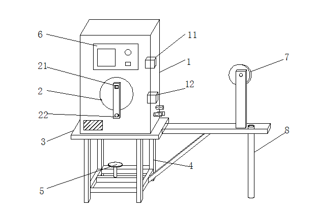
1. a tester for tension and torsion of a probe cable , Including the shell of the testing machine (1), The inside of the testing machine housing (1) is provided with a servo motor (11) and a turbine reducer (12), It is characterized in that the front end of the testing machine housing (1) is provided with a control panel (6), A fixture plate (2) is arranged below the control panel (6), The bottom of the shell (1) of the testing machine is connected with a base (3), The four corners of the base (3) are supported by a support (4), And the center below the base (3) is connected with a cylinder tray (5) through the support (4), The right end of the base (3) extends out of another bracket (4), The upper surface of the support (4) is connected with a pulley (7) through a support rod (7).
According to claim 1, the 2. is characterized in that the clamp plate (2) is connected with a clamping fixture (21) through a support rod, and the lower end of the support rod is provided with a rotating fixture (22).
The 3., according to claim 1, is characterized in that the pulley (7) has a radius of 100 mm, and a 120 alumina sand cloth (71) installed according to the curvature radius of the pulley (7).
The 4., according to claim 1, is characterized in that the bottom of another support (4) extending from the right end of the base (3) is welded with a guide tube (8), the guide tube (8) penetrates the support (4), and the guide tube (8) is arranged at 100 mm on the right side of the support rod.
A Test Machine for Tension and Torsion Resistance of probe cable
Technical areas
The utility model relates to the technical field of a probe cable testing machine, in particular to a probe cable tensile force torsion wear-resistant testing machine.
Background technology
With the development of economy and technology, the probe cableis used more and more widely in the process of construction and testing, especially in the detection of high-voltage electricity, which often leads to accidents due to the breakage of wire.
Content of utility model
The purpose of the utility model is to provide a tensile torsion wear-resistant testing machine for the probe cable, so as to solve the problems raised in the background technology.
In order to achieve the above purpose, the utility model provides the following technical scheme: a watch pen wire tensile force torsion wear-resistant testing machine comprises a testing machine shell, the inside of the testing machine shell is provided with a servo motor and a turbine reducer, the front end of the testing machine shell is provided with a control panel, the bottom of the control panel is connected with a base, the four corners of the base are supported by a support, and the center of the base is connected with a cylinder tray through the support, the right end of the base extends out of another support, and the upper surface of the support is connected with a pulley through the support rod.
The clamping fixture is connected with the clamping fixture through the support rod, and the lower end of the support rod is provided with a rotating fixture.
Optionally, the pulley radius is 100 mm, and the pulley is provided with 120 alumina sand cloth installed according to the curvature radius of the pulley.
A guide tube is welded at the bottom of another support extending from the right end of the base, and the guide tube is arranged at 100 mm on the right side of the support rod.
Compared with the prior art, the utility model has the advantages that: the watch pen wire tensile force torsion wear-resistant testing machine is used to place weights during the pull test of the test machine through a cylinder tray arranged at the bottom of the base, driven by a servo motor and a turbine reducer to achieve the effect of arbitrary left and right swing angle, and the table pen probe will not shift during the experiment by setting a clamping fixture in the fixture plate. In the pull bending test, the rotating fixture can meet the test requirements of different dangerous conditions by installing the rotating fixture in the fixture plate; In the friction test ,120 alumina sand cloth is installed on the pulley according to the curvature radius of the pulley to prevent the cable from swinging. At the same time, the guide tube is welded in the support to make the weight run in the guide tube. Prevent weight from shaking.
Description
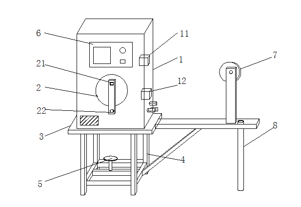
Fig .1 is a schematic diagram of the structure of the utility model;
Fig .2 is a drawing test diagram of the utility model;
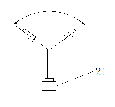
Fig .3 is a schematic diagram of the tensile bending test of the utility model;
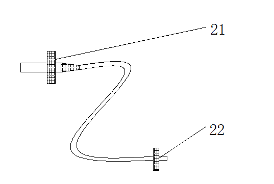
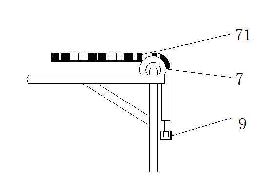
Fig .4 is a schematic diagram of the friction test of the utility model.
figure :1 testing machine shell ,11 servo motor ,12 turbine reducer ,2 clamp plate ,21 tightening fixture ,22 rotating fixture ,3 base ,4 support ,5 cylinder tray ,6 control panel ,7 pulley ,71 sand cloth ,8 guide tube.
Specific implementation modalities
The following will be a clear and complete description of the technical scheme in the embodiment of the utility model in combination with the attached drawings in the embodiment of the utility model. Obviously, the described embodiment is only a part of the embodiment of the utility model, not all embodiments. Based on the embodiment of the utility model, all other embodiments obtained by ordinary technicians in the field without making creative labor belong to the scope of protection of the utility model.
See Figure 1-4, The utility model provides a technical scheme: a test machine for tension and torsion wear resistance of a watch pen wire, Including testing machine housing 1, The inside of the test housing 1 is provided with a servo motor 11 and a turbine reducer 12, Control servo motor 11 and turbine reducer 12 by controller, To achieve any swing angle, The front end of the test housing 1 is provided with a control panel 6, A fixture plate 2 is arranged below the control panel 6, The clamp plate 2 is connected with a clamping fixture 21 through a supporting rod, By setting the clamping fixture 21 in the fixture plate, So that the pen probe does not shift during the experiment, The lower end of the support rod is provided with a rotary fixture 22, In the pull bending test, By installing the rotary fixture 22 inside the fixture plate, To meet the test requirements of different risks, The bottom of the test housing 1 is connected with a base 3, The four corners of the base 3 are supported by the support 4, And the center of base 3 is connected with cylinder tray 5 through bracket 4, The meter pen wire tension torsion wear-resistant tester passes through the cylinder tray 5 at the bottom of base 3, Used to place weights in the test machine during pull test, The right end of the base 3 extends out of another bracket 4, And the upper surface of the support 4 is connected with a pulley 7 through the support rod, A pulley 7 has a radius of 100 mm, And the pulley 7 has 120 alumina sand cloth 71 installed according to the radius of curvature of pulley 7, In friction tests, By having a No .120 alumina sand cloth mounted on the pulley 7 according to the radius of curvature of the pulley, To prevent the cable from swinging, The bottom of another bracket 4 extending from the right end of the base 3 is welded with a guide tube 8, The guide tube 8 penetrates the support 4, And the guide tube 8 is located at 100 mm on the right side of the support rod, Welding guide tube 8 in support, Make the weight run in the guide tube 8, Prevent weights from shaking.
Although embodiments of the utility model have been shown and described, for ordinary technicians in the field, it can be understood that a variety of changes, modifications, replacements and variants of these embodiments may be made without departing from the principle and spirit of the utility model, and the scope of the utility model is limited by the attached claim and its equivalent.


Reviews
There are no reviews yet.