


- Description
- Reviews (0)
Description
Detail Information
temperature rise test equipment
,
led testing equipment
Product Description
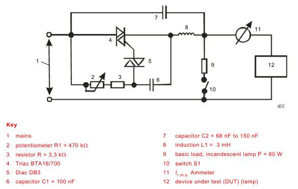
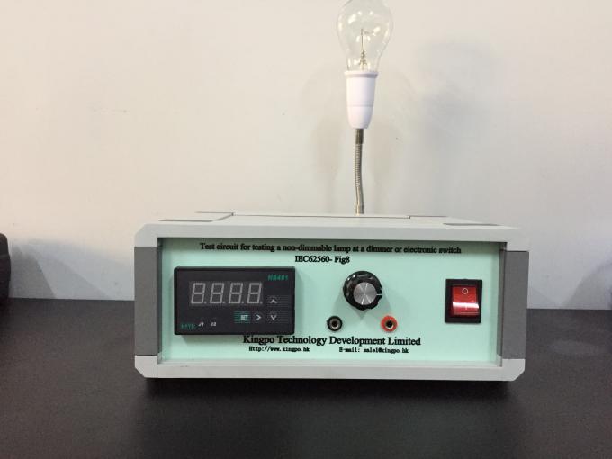
Test Circuit For Testing a Non-Dimmable Lamp at a Dimmer or Electronic Switch
1. Use
Applying non-dimmable self-ballasted lamps on a dimmer or an electronic switch is to be tested as a possible case of abnormal operation..
2. Reference standards
IEC60560-Fig8
4. Technical parameters
| Internal dimension | 105 X 267 X220 W *D*H mm |
| 2 | potentiometer R1 |
| 3 | resistor R |
| 4 | Triac BTA16/700 |
| 5 | Diac DB3 |
| 6 | capacitor C1 = 100 nF |
| 7 | capacitor C2 = 68 nF to 150 nF |
| 8 | induction L1 = 3 mH |
| 9 | basic load, incandescent lamp P = 60 W |
| 11 | I r.m.s. Ammeter |
| Ammeter input Power | AC 220V 50Hz |
Test procedure:
Determine R1 and S1 setting at which the maximum I r.m.s . occurs.
Test at this situation, and if the lamp passively fails within 60 min, repeat the test at 10 % lower I r.m.s . The lower I r.m.s . shall be set in the decreasing potentiometer resistance direction.


Reviews
There are no reviews yet.