

RD4L IT Test Equipment Battery Capacity Voltage Discharge Resistant Tester
Product Details:
| Place of Origin: | China |
| Brand Name: | KingPo |
| Certification: | Calibration Certificate |
Payment & Shipping Terms:
| Minimum Order Quantity: | 1 |
|---|---|
| Price: | To be quoted |
| Packaging Details: | safety carton pack or plywood box |
| Payment Terms: | T/T |
- Description
- Reviews (0)
Description
Detail Information
av test equipment
,
tv test equipment
Product Description
RD4L IT Test Equipment Battery Capacity Voltage Discharge Resistant Tester
Battery capacity voltage discharge resistant tester RD4L
1 Introduction
1.1. Title
Residual Discharge Automatic Test Software 1.0 Instruction Manual.
1.2. Purpose
The purpose of this document is to explain how to use the residual discharge automatic test software V1.0 ;make it easier for users to operate.
2. The main program control and display interface
Residual discharge automatic test software V2.0 shows the main control and display interface as shown in Figure 1.
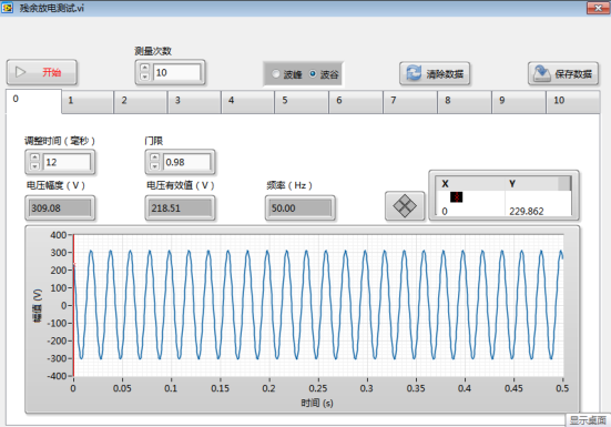
2.1. First row of controls
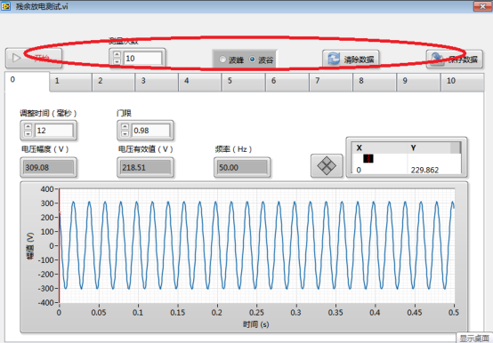
The controls are shown in Figure 2, including the start button, measurement times, crest/valley selection bar, clear data button, and save data button. The specific meaning is as follows:
Start button: control the beginning of the residual discharge test, press to start the test;
Number of measurement input field: set the number of measurements (maximum 10);
Peak/valley selection field: Select peak experiment or wave valley experiment;
Clear Data button: Clear the test data on the page;
Save Data button: Saves the test results (data and waveforms) to the test data folder on the D drive.
2.2. Tab
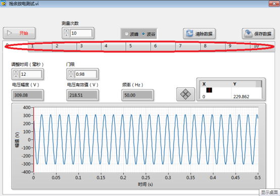
The control is shown in Figure 3. There are a total of 11 tabs. Tab 0 shows the waveform of the test voltage and some settings for the test. Tabs 1 to 10 show the results of each test.
2.2.1. Tab 0
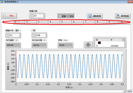
Tab 0 As shown in Figure 4, it includes time adjustmentinput controls, threshold input controls, voltage amplitude display controls, voltage rms display controls, frequency display controls, and waveform diagram controls. The specific meaning is as follows:
Adjust the time input control (milliseconds): set the adjustment time to offset the change of the reaction time of the relay and the program running time with the unit of time ms, here set to 12;
Threshold input field: set the threshold, that is, when the absolute value of the momentary value of the power supply voltage when the relay is off> the peak value of the power supply voltage × the threshold value, the system considers that the power supply is disconnected at the peak/valley of the voltage, that is, the test is successful. Otherwise, the test fails, and the software automatically re-tests until the test is successful. This is set to 0.98.
Voltage amplitude display control (V): Display the amplitude of the power supply voltage, unit V; Voltage RMS display control (V): Display the effective value of the power supply voltage, unit V; Frequency display control (Hz): Display the frequency of the power supply, unit Hz; Waveform control: Displays the waveform of the power supply.
2.2.2. Tabs 1~9
The contents of tabs 1 to 9 are the same. Here, tab 1 is used as an example. Tab 1 includes the disconnected voltage (V) indicator, the 1s post-voltage (V) indicator, the 2s post-voltage (V) indicator, the 37% voltage (V) indicator, and time of 37% (Figure 5). ) Display Controls, Vernier Time (s) Display Controls, Vernier Voltage (V) Display Controls, Vernier Voltage (%) Display Controls, and Waveform Controls. The specific meaning is as follows:
Disconnect voltage (V) indicator: Displays the instantaneous value of the voltage when the power is off, unit V;
1s after the voltage display control (V): shows the voltage value of power interface of the tested device 1s later after the power supply voltage is disconnected, unit V;
37% voltage (V) display control: instantaneous value of the voltage 2s later when the power supply is disconnected ×37%, unit V;
Time of 37 % (s) display control: when the power supply is disconnected, the voltage value of the power interface of the test device is reduced to 37% of the voltage when the power is disconnected.Unit s;
Cursor time display control (s): display cursor's abscissa (time) unit s;
Vernier voltage (V) display control: The vertical axis (voltage) of the waveform at the cursor is displayed in V;
Vernier voltage (%) display control: The vertical axis (voltage) of the waveform at the cursor is displayed as a percentage of the voltage when the power is turned off, in %; Waveform control: Displays the test waveform.
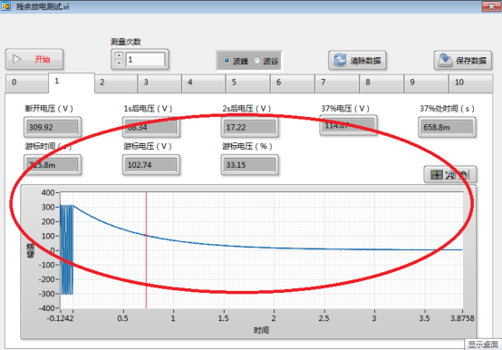
Figure 5
3. How to use the software
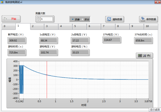
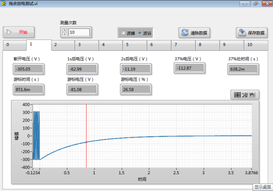
First set the waiting time (default 12), threshold (default 98), number of measurements, determine the peak or valley measurement, and then click the start button, the software will automatically complete all measurements. The test results are shown in the figure. Finally, click the Save Data button to save the test results.


Reviews
There are no reviews yet.