

RDL-318 Television Transmission System , Digital Tv Signal Tester
Product Details:
| Place of Origin: | China |
| Brand Name: | KingPo |
| Certification: | Calibration Certificate |
Payment & Shipping Terms:
| Minimum Order Quantity: | 1 |
|---|---|
| Price: | To be quoted |
| Packaging Details: | safety carton pack or plywood box |
| Payment Terms: | T/T |
- Description
- Reviews (0)
Description
Detail Information
tv test equipment
,
tv signal tester
Product Description
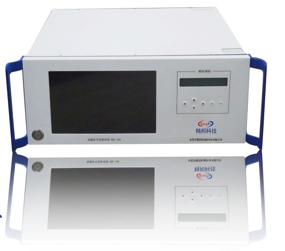
RDL-318 TV Signal Transmission System
1 General
1.1 Introduction:
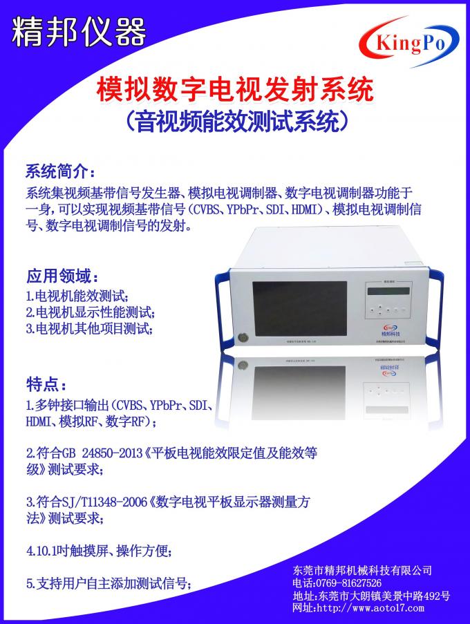
The product is used to test digital TV. It provides test signals for the experiment of TV test. The product can produce test signal of CVBS, YPbPr, SDI, HDMI and RF antenna interface to meet the test requirements of major TV interfaces.
1.2 Application:
1. TV energy efficiency testing;
2. TV display performance testing;
3.TV other testing;
1.3 Features:
1.3.1 Video signal:
| Interface | Composite,Component(YPbPr),SDI,HDMI |
| Video Format | PAL,NTSC,1920×1080 50i,1920×1080 50p,1920×1080 60i,1920×1080 60p etc. |
1.3.2 ATV RF signal:
| Interface | BNC,F-TYPE |
| Standard | PAL-DK |
| Output Impedance | 75Ω |
| Output Frequency Range | 47~862MHz |
| Output Level |
BNC:70~90dBμV F-TYPE:100 ~120dBμV |
1.3.3 DTV RF signal:
| Interface | BNC,N-TYPE |
| Standard | DTMB,DVB-C,DVB-T,DVB-S |
| Output Impedance |
BNC:75Ω N-TYPE:50Ω |
| Output Frequency Range | 32~2186MHz |
| Output Level |
BNC:-60dBm N-TYPE: -60 ~0dBm(DVB-C,DVB-S) -63 ~-3dBm(DTMB,DVB-T) |
| MER | >40dB |
2 Operation
2.1 Video setting
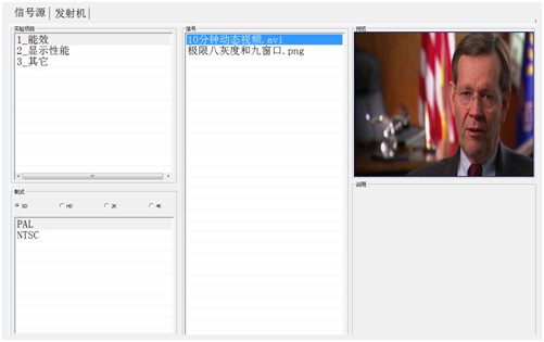
Software interface is shown in Figure 1, including experimental projects, video formats, signals and preview for four parts. Specific meaning as follows:
Experimental Projects: Different experimental projects match different signal classifications; The user selects the corresponding experimental project according to the specific test;
Video Formats: Display a signal format selecting by users , including PAL, NTSC, 1920 × 1080i 50Hz / 60Hz, 1920 × 1080p 50Hz / 60Hz, etc;
Signals: Display a signal selecting by users;
Preview: Display a preview image of the current playback signal.
1
2. DTV RF Setting
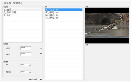
Software interface is shown in Figure 2, including experiment projects, RF parameters, modulation parameters, signals and preview for five parts. Specific meaning as follows:
Experiment Projects: Different experimental projects match different signal classifications; The user selects the corresponding experimental project according to the specific test;
RF Parameters: Users can set the level and frequency of the RF;
Modulation Parameters: Users can set the digital television modulation parameters;
Signals: Display a signal selecting by users;
Preview: Display a preview image of the current playback signal.
2
3. ATV RF Setting
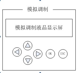
Related Set ATV RF signal is achieved by mechanical buttons and LCD screen, as shown in Figure 3. The liquid crystal display shows the current menu contents; there are four navigation buttons on the left. Up and down buttons are used to select menu, left and right buttons are used to adjust the parameters; A OK button is used to implement input parameters; A ESC key is used to return to the previous menu.


Reviews
There are no reviews yet.